The Micro Drone 3 from Extreme Fliers is a capable little quadcopter but is suffers from fried PCB boards. This guide is to assist you with replacing the flight controller board and a motor arm on your quadcopter, it takes less than 10 minutes via these simple steps.
It is frustrating, after many happy flights with your MD3, it suddenly drops to the ground. You smell and possibly even see smoke coming from the quadcopter and you know that its time to replace the PCB.
This issue is harmless in terms of your own health and safety but it will result in your quadcopter becoming unflyable. Extreme Fliers have worked hard to eradicate this fault but it seems to reoccur. In addition, I also had a faulty motor arm and so the guide includes replacement of this as well.
Buying the spares…
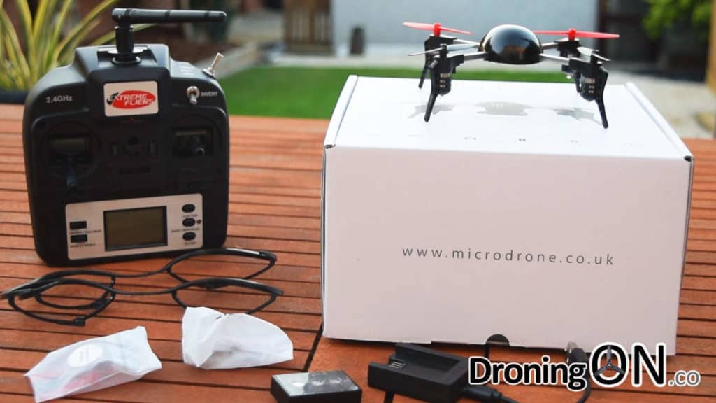
Firstly you will need to head to the Micro Drone website which would appear to be the only stockist of spares at this time, the spares that I used are as follows (be sure to select the correct option when ordering as there are variants):
- Spare PCB Board – /spare-parts/products/replacement-cpu
- Spare Motor Arms – /collections/products/parts-md-3-0
How to guide…
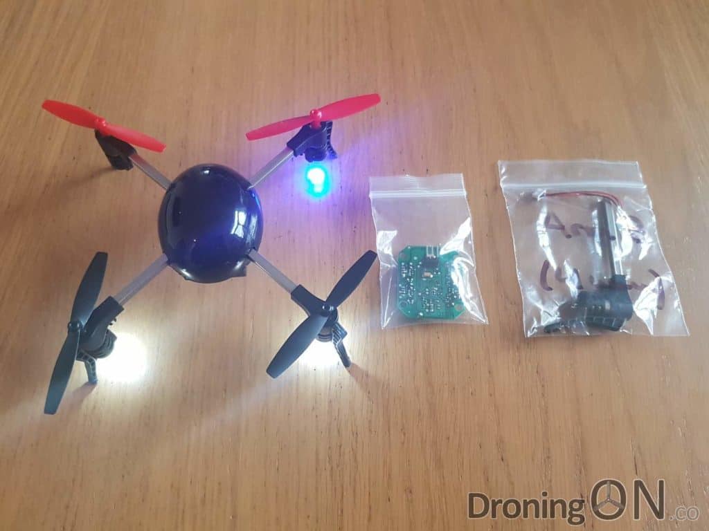
Get your Micro Drone 3 ready with the spare parts and remove the battery from the quadcopter.
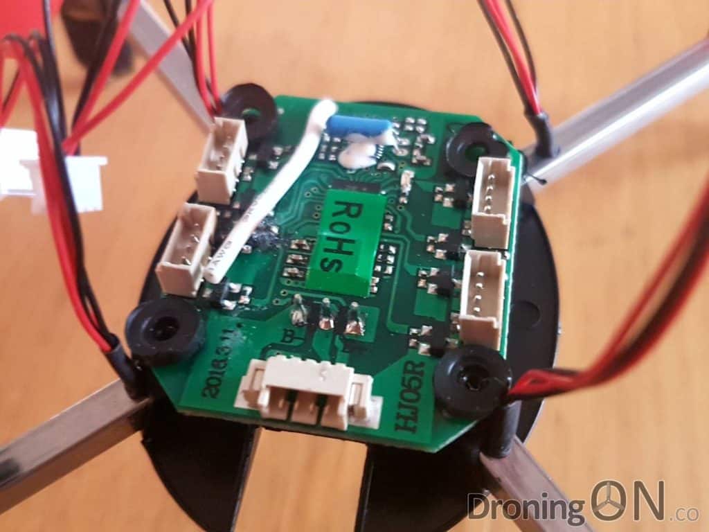
Carefully pop the top cover off the Micro Drone 3 to reveal the circuit board (PCB), using a small screw-driver prise out the 4 motor plugs connected to the board.
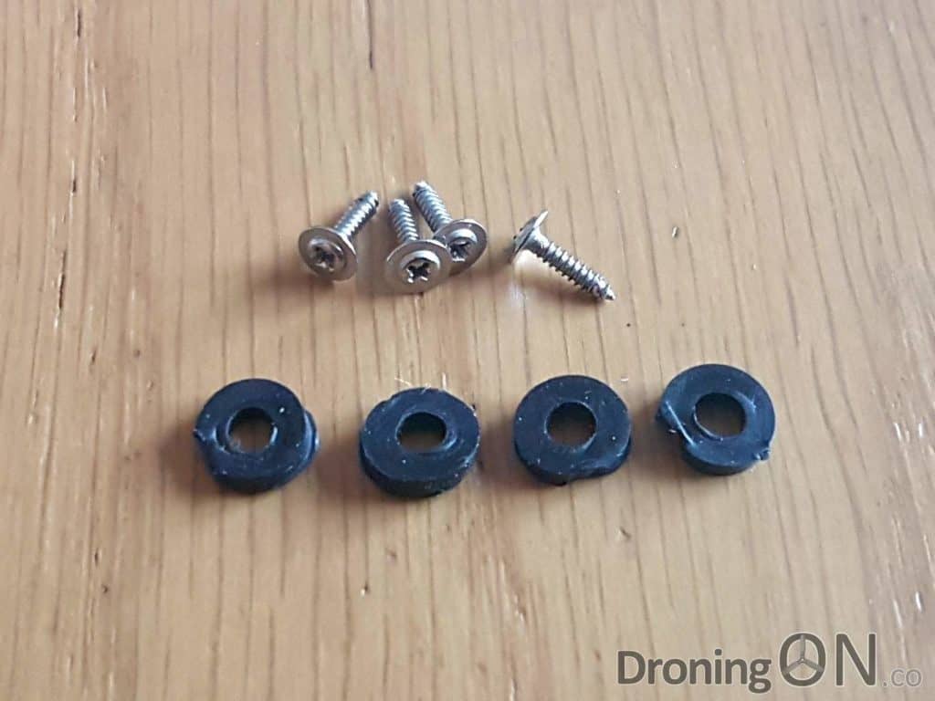
Using a screw-driver, unscrew the four screws which secure the PCB to the main body of the quadcopter. The heads of these screws are not particularly well machined, therefore I found it easier to use a straight-screwdriver rather than a posi-drive.
Extreme Fliers have since informed me that they have uprated the screws used to a better quality.
With the four screws and rubber grommets removed, the PCB board is now free to lift out of place, in addition the motor arms will also now slide out of place.
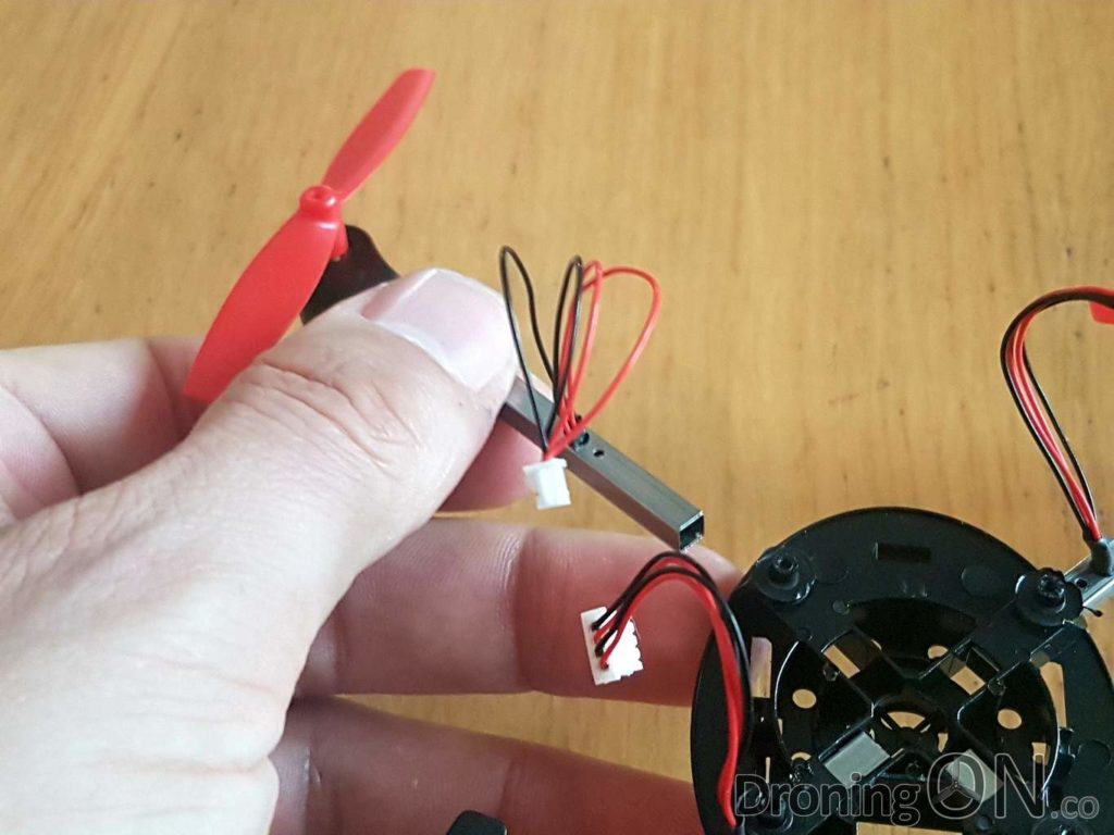
Pull the faulty motor arm out of the chassis and set to one side. It is worth keeping this faulty motor unit for spares, you never know when a part of it might become useful. Retain the prop as it will be fitted to the replacement motor arm.
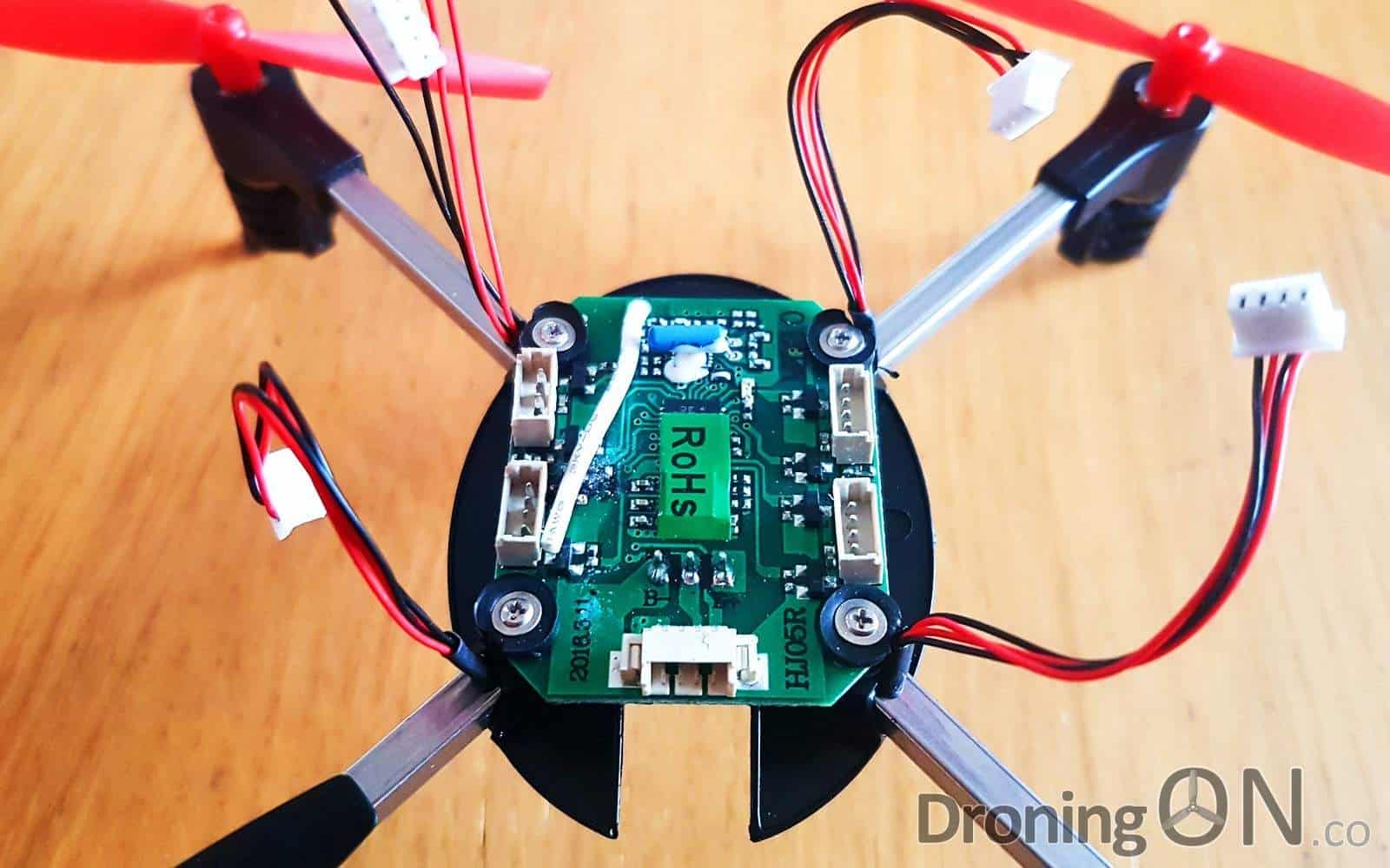
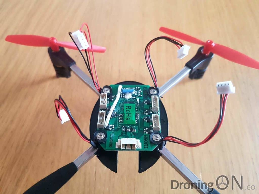
Install the new PCB board in place and ensure that it slots cleanly over the small black extruded screw-holes on each corner of the board.
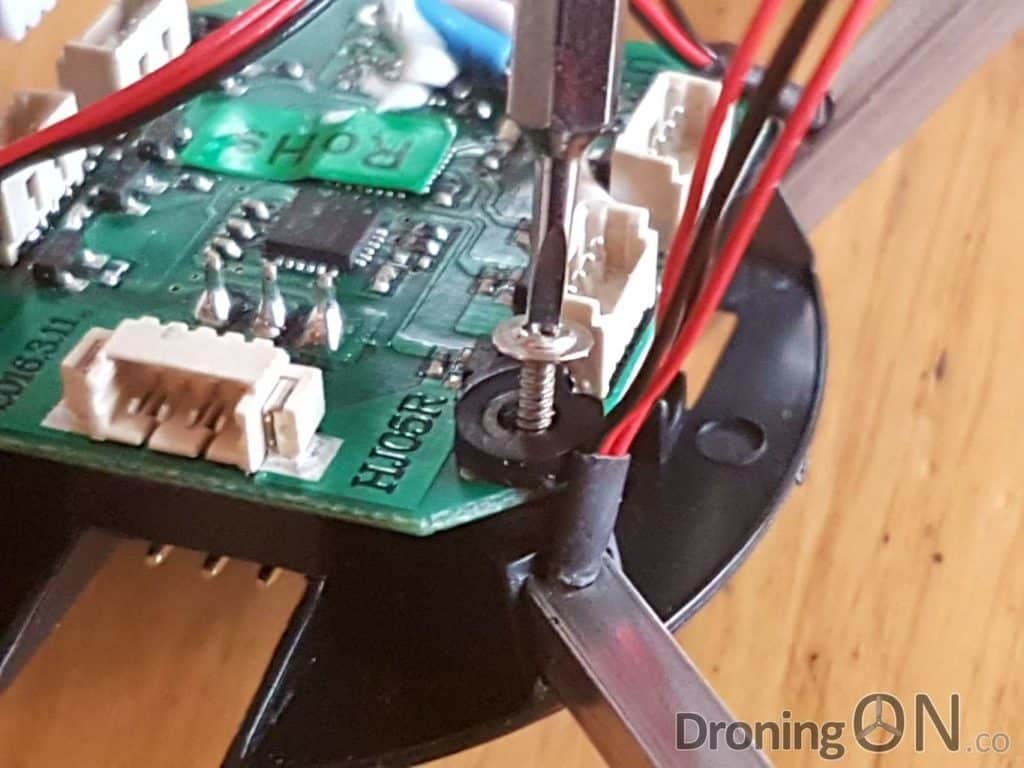
Insert the replacement motor arm and ensure that it is fully pushed into place. Then place a rubber grommet in position and then insert a screw through and into the extruded screw-hole.
Do not tighten the screw until you have applied pressure to the end of the motor arm to ensure that the screw goes in through the chassis and into the pre-drilled hole of the motor arm.

Tighten the screw, it should not feel overly resistant, if it does then you may not have aligned the motor arm correctly. Do not over-tighten the screw to avoid damaging the PCB or stripping the head.
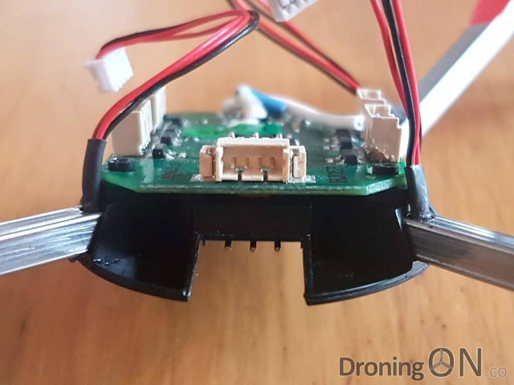
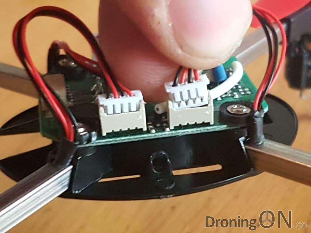
Finally, reinsert each of the motor connectors into the PCB board. Ensure that the connectors are the correct way around (as illustrated) and do not force them into position as that risks bending the fragile pins.
Before connecting power to the repaired Micro Drone 3, remove all props and ensure that the motors work as expected. The reason for removing the props is to ensure that no additional fault causes the props to spin up fully unexpectedly.
Only when confident that the repaired quadcopter is working should you re-attach the props. When doing so, ensure that you attach them in the correct direction.
Be sure to join the DroningON Discussion Group for the latest news, reviews and information from the drone and quadcopter community!